Optimal Region Connections
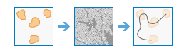
This tool calculates the optimal connectivity network between two or more input regions.
Example applications include the following:
- Suitability modeling—From a suitability model, you have identified 10 of the best habitat patches for bobcats. You want the bobcats to be able to move between the patches through the most effective network of wildlife corridors to maintain genetic diversity within the metapopulation.
- Timber harvest—In a timber harvest, you want to create the most cost-efficient network of logging roads from which to extract the lumber.
- Peacekeeping—In a military peacekeeping deployment, you have identified five areas at which to position troops and personnel. You want to develop the optimally connected supply routes between the bases.
If Use current map extent is checked, only those locations in the input layers that are visible within the current map extent will be analyzed. If unchecked, all locations in both input layers will be analyzed, even if they are outside the current map extent.
Choose region raster or feature
The input regions to be connected by the optimal network.
If the region input is a raster, the regions are defined by groups of contiguous (adjacent) cells of the same value. Each region must be uniquely numbered. The cells that are not part of any region must be NoData. The raster type must be integer, and the values can be either positive or negative.
If the region input is a feature, it can be points, lines, or polygons. Polygon regions cannot be composed of multipart polygons.
Choose barrier raster or feature (optional)
The dataset that defines the barriers.
For a raster, the input type can be integer or float. Any cells that have a value (including zero) will be treated as a barrier. Any cells that are NoData will not be treated as a barrier.
For a feature, the input can be point, line, or polygon.
Choose cost raster (optional)
A raster defining the impedance, or cost, to move planimetrically through each cell.
The value at each cell location represents the cost-per-unit distance for moving through the cell. Each cell location value is multiplied by the cell resolution while also compensating for diagonal movement to obtain the total cost of passing through the cell.
The values of the cost raster can be integer or floating point, but they cannot be negative or zero (you cannot have a negative or zero cost).
Distance method (optional)
Specifies whether to calculate the distance using a planar (flat earth) or a geodesic (ellipsoid) method.
- Planar—The distance calculation will be performed on a projected flat plane using a 2D Cartesian coordinate system. This is the default method.
- Geodesic—The distance calculation will be performed on the ellipsoid. Therefore, regardless of input or output projection, the results do not change.
Connections within regions (optional)
Specifies whether the paths will continue and connect within the input regions.
- Generate connections—Paths will continue within the input regions to connect all paths that enter a region. This is the default.
- No connections—Paths will stop at the edges of the input regions and will not continue or connect within them.
Result optimal connectivity lines feature layer name
The name of the layer that will be created in My Content and added to the map. The default name is based on the tool name and the input layer name. If the layer already exists, you will be prompted to provide another name.
This layer is an output line feature that connects each input region.
Each path (or line) is uniquely numbered, and additional fields in the attribute table store specific information about the path. Those additional fields are the following:
- PATHID—The unique identifier for the path
- PATHCOST—The total accumulative distance or cost for the path
- REGION1—The first region the path connects
- REGION2—The other region the path connects
Since each path is represented by a unique line, there will be multiple lines in locations where paths travel the same route.
You can specify the name of a folder in My Content where the result will be saved using the Save result in drop-down box.
Result neighboring connections feature layer name (optional)
The name of the layer that will be created in My Content and added to the map. The default name is based on the tool name and the input layer name. If the layer already exists, you will be prompted to provide another name.
This layer is an output line feature that identifies all paths from each region to each of its closest, or least cost, neighbors.
Each path (or line) is uniquely numbered, and additional fields in the attribute table store specific information about the path. Those additional fields are the following:
- PATHID—The unique identifier for the path
- PATHCOST—The total accumulative distance, or cost, for the path
- REGION1—The first region the path connects
- REGION2—The other region the path connects
Since each path is represented by a unique line, there will be multiple lines in locations where paths travel the same route.
You can specify the name of a folder in My Content where the result will be saved using the Save result in drop-down box.